tioga revolvers, how to fit/whats missing- pics up

ishaw

Gold Trader
GT Fan
Feedback
View
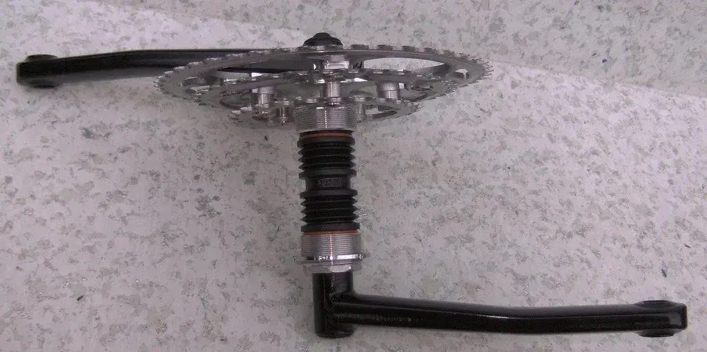
This may sound like a daft question, but just received a nice set of these cranks (nos but with storage marks), but I can't quite figure out how the spider is held on. Has anyone any experience in fitting these that can take me through it?

I was also looking at the bearings in order to get a set for spares, but was surprised at how little contact there is with the axle I.e. to me it is loose and not like fitting an ht2 bb. Is this normal or are the bearings the wrong size?

Last thing - any advice on spares and keeping them on the road. As they are nos, should be ok for now, but would like to know what to do and where to go when the time comes.

Thanks

Ian
 
i had early one (110pcd) and the spider bolted to the crank arm. the axle was snug like a ht2 so could be wrong bearings?

failing that sell it to me :wink: been wanting another for years,gave mine away before i found retrobike :roll: :evil:
 
Thanks for the reply. Selling them could be an option as I bought them with a build in mind which has now changed more times than I care to imagine, but anyhow, I thought I'd take some pics and post them up to see if anyone can help me figure out how to put this together.

Spider:
IMG_3443.jpg


Close up of spider hole that slots into the stud on the arm:
IMG_3444.jpg


Arm stud - note no thread:
IMG_3445.jpg

IMG_3446.jpg


Spider and arm mated together:
IMG_3447.jpg

IMG_3448.jpg


With the BB cup pushed down. The bearing has slight 'play' as per a worn/loose cup/cone hub:
IMG_3449.jpg


This is NOS so I was expecting everything to be tight, but maybe I am just missing something? The bearing can be spun on the axle without actually engaging the bearing i.e. the whole bearing spins rather than the inner part. It has play when you rock it from side to side on the axle.

I'm also baffled as to how the spider is fixed to the arm, as there is no way of tightening anything up. Surely it can't all rely on the pressure of the bearing cups against it can it?

Any help appreciated as I planned to fit this on a pace or my ti dbr, but I keep changing my mind and the confusion around how on earth I fit it all together is making me less inclined to use it.

Cheers again

Ian
 
It can't have the bearing cup pressing against the back of the spider or it won't rotate! :shock:

Looking at your photo's I'm guessing there's a slight taper on the axle? Imagine you install the drive side cup first, then as you install the spindle from the non-drive side does it seat itself or not? Or do you have to 'tap' it home with a rubber mallet? Then the spider will only go onto the spindle so far (if it is tapered) and is then held in place by the splined crank?

All guesswork as Googling it has revealed b@ggerall so far... :?
 
We_are_Stevo":28zpy4r7 said:
It can't have the bearing cup pressing against the back of the spider or it won't rotate! :shock:

Looking at your photo's I'm guessing there's a slight taper on the axle? Imagine you install the drive side cup first, then as you install the spindle from the non-drive side does it seat itself or not? Or do you have to 'tap' it home with a rubber mallet? Then the spider will only go onto the spindle so far (if it is tapered) and is then held in place by the splined crank?

All guesswork as Googling it has revealed b@ggerall so far... :?
Cheers for the help. The spider can slip all the way along the axle so I don't think it is tapered, no mallets or hitting required, everything slips together very easily.

As for Google, it has been no help at all hence the plea for advice :cry:
 
We_are_Stevo":1b1f349y said:
Do you have the spacer in the middle as in the pix in this eBay listing?

http://cgi.ebay.ph/ws/eBayISAPI.dll?Vie ... 0857445323

second from bottom pic...
Ah, now things are clicking into place in my head. With the spacer, it would allow everything to be pulled together. I think then the spider would be pushed/pulled tightly to the bearing within the crank cup (the cup has an exposed bearing so would not stop the spider spinning).

Sadly, the cranks I've bought don't have this, or the other spacers listed that I assume allow it to be run with 68 or 73mm bb shells.

Thanks for the searching, seems to be you have found the missing piece, unless there is more to this puzzle?
 
i had a set on my shogun some time ago and the spider and crank arm just slot together by compression re the ahead set method...i had a slight play in the axle as well from what i recall...i had my arm replaced as i broke the stud on the crank arm when sprinting hard....i then had them stove enamelled white...looked real good too...
 
maybe this helps


Lars
 

Attachments

  • BILD0088.webp
    BILD0088.webp
    82.5 KB · Views: 911
  • BILD0081.webp
    BILD0081.webp
    60.3 KB · Views: 910
Hi Lars, that's perfect, so it seems I'm missing the three spacers that fit between the crank arm and cup. You don't happen to have ant measurements for these do you, as I'm going to need to hunt some down.

Thanks

Ian
 

Latest posts

Back
Top