Uncle Grumpy
Retro Guru
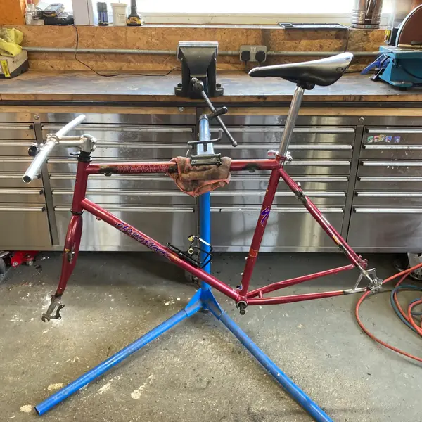
Further to the above... here's a bit of process related stuff...
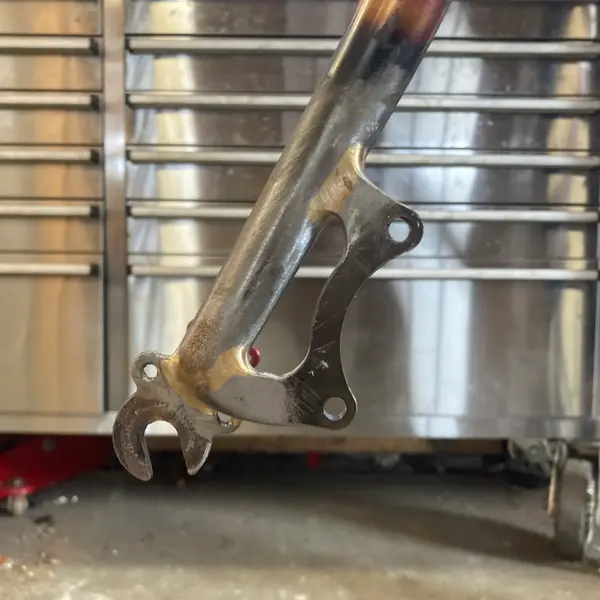
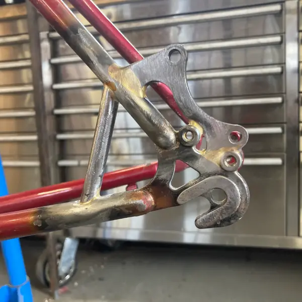
I used a wheel and clamped a cable disc caliper to the rotor, "bolted" some cardboard to the mount to give me a rough template. Also did the same for the support brace to get it roughed in. In the photo below, it's been cut and trimmed to make it a little sexier than a squared piece of steel.

I transferred the cardboard template across to some steel to make the mount, also using some international standard dimensions that you can track down on the interwebs.
I also made a jig to mount the mount so the mount could be mounted. There are commercially available ones available, but I used threaded rod, nuts and also a rotor to check alignment.
Then comes the marking, trimming, test fitting, trimming, test fitting, trimming... etc. Measure twice, cut once? Bullsh*t. Measure once carefully and trim dozens of times until you get it sitting right. Grind off a little at a time. I should point out that this is all done with fairly basic tools, scribe, rule, angle grinder with cutting wheel and another with a flap disc, disc sander, bench grinder, various hand files, pedestal drill, proper drill bits, emery paper, centre punch and hammer, and a solid vise.
These are of course what I consider to be basic tools. I own lots more tools, but owning anything less than the types of tools listed above indicates a character flaw and I would be wary of you if we passed on the street.
Oh, and a brazing set up. You could also use a TIG welder. You could get away with a MIG if the frame was made out of chunky 4130 - not so anything thin walled. I'd try to avoid using a stick welder. I used a Bullfinch torch and BBQ gas.
Part 2 to follow...
I used a wheel and clamped a cable disc caliper to the rotor, "bolted" some cardboard to the mount to give me a rough template. Also did the same for the support brace to get it roughed in. In the photo below, it's been cut and trimmed to make it a little sexier than a squared piece of steel.

I transferred the cardboard template across to some steel to make the mount, also using some international standard dimensions that you can track down on the interwebs.

I also made a jig to mount the mount so the mount could be mounted. There are commercially available ones available, but I used threaded rod, nuts and also a rotor to check alignment.

Then comes the marking, trimming, test fitting, trimming, test fitting, trimming... etc. Measure twice, cut once? Bullsh*t. Measure once carefully and trim dozens of times until you get it sitting right. Grind off a little at a time. I should point out that this is all done with fairly basic tools, scribe, rule, angle grinder with cutting wheel and another with a flap disc, disc sander, bench grinder, various hand files, pedestal drill, proper drill bits, emery paper, centre punch and hammer, and a solid vise.
These are of course what I consider to be basic tools. I own lots more tools, but owning anything less than the types of tools listed above indicates a character flaw and I would be wary of you if we passed on the street.
Oh, and a brazing set up. You could also use a TIG welder. You could get away with a MIG if the frame was made out of chunky 4130 - not so anything thin walled. I'd try to avoid using a stick welder. I used a Bullfinch torch and BBQ gas.
Part 2 to follow...
Last edited: