2000 Marin Mount Vision Build

Re:

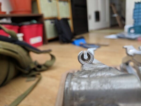
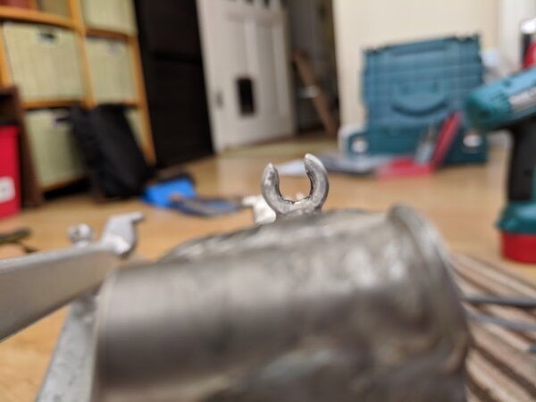
All 4 of the Marins my wife, my 2 daughters and myself own have a short length of 8mm round bar threaded on both ends, with flanged nuts, like they have integral washers. This is the standard Marin fitting. I can get a socket on nuts no bother, and just checked the socket on one of nuts and it is a 1/4" drive 10mm socket. Looks like the nuts are reduced in size across the flats but still having the 8mm thread internally. I wouldn't use threaded bar in case it cuts in to alloy of swingarm or shock spacers. You should be able to find a long enough 8mm bolt that you can cut down to length then thread other end. Seems like the nuts might be a problem though.
As to the flanged/top hat washers that fit into holes on mount on frame end of shock, there was a thread on here somewhere about a rebuild of a full suss Marin that if I remember correctly the guy had some made. Have a wee search.

Your only other option is to find a cheapo/knackered frame that has the bits you need. Like this https://www.ebay.co.uk/itm/1997-Marin-M ... Sw3SFdMu3W
 
When you click on links to various merchants on this site and make a purchase, this can result in this site earning a commission. Affiliate programs and affiliations include, but are not limited to, the eBay Partner Network.
Thanks for the info, that's helpful. Don't know what happened to the shock mounting fixtures that would have come with the frame!

Unfortunately I think I might struggle to source an M8 nut with 10mm flats, but will have a look online as that's definitely a possible solution.

Another possibility is to use an 8mm external diameter sleeve nut with an M6 internal thread at either end of the shock mount, with a piece of M6 threaded bar in between, and a piece of 8mm external diameter tube cut to size to fill the distance between the sleeve nuts.
 
Right, just ordered some M6 8mm external diameter sleeve nuts and some M6 threaded bar. I think I should be able to fabricate something suitable out of this, and it should look reasonably smart too (as opposed to the horrid DIY bodge currently half completed on the frame).
 
I was looking to see why the mounting hardware I ordered hasn't arrived yet, and turns out I mistakenly ordered the sleeve nuts from a Chinese seller on amazon - whoops! Since they'll probably be another couple of weeks coming, I turned my attention to the next job on the list, converting the old cable brake stops into hydraulic hose guides.

I started with a 3.5mm drill bit and worked my way up to a 5.5mm bit in 0.5mm increments. In principle this should have been an easy five minute job, but the tight angles on the frame made things very fiddly (and a bit stressful!). A dremel with a flexible drive shaft would have made life a lot easier.

I then used a combination of a triangular and flat file to enlarge the slot in the brake stop so that a hydraulic hose will just about squeeze through. Again, I expected this to be a quick and easy job, but with no room to move the file, I was limited to the end ~1cm of the tool available for use while working on the main frame, so it took quite a while. A flexible drive dremel with a router-type cutting bit would have been ideal for the job if I had one.

Finished up with some 400 grit sandpaper to deburr and smooth off, and I think it's looking good now. The fit is (intentionally) pretty tight for the hydraulic hose, which should limit movement and rattling, but I'll have to check carefully that the new hose guides aren't going to wear away at the hose exterior when I build it up.

Here's what the cable stops looked like initially:


And here's the finished result:


I know it doesn't look like much, but doing the four cable stops / hose guides took me a good couple of hours.
 

Attachments

  • Brake stop before.jpg
    Brake stop before.jpg
    43.2 KB · Views: 922
  • Brake stop after.jpg
    Brake stop after.jpg
    40.8 KB · Views: 922
More excitingly, the fork for the build arrived a couple of days ago - an RST Delta TL, courtesy of fellow retrobiker scant.


Haven't taken them to bits yet (and probably won't bother as they feel in great working order), but I'm pretty sure they will be spring / MCU elastomer driven, with an air/oil damper

They feel (and sound, as you can really hear the damper in action!) a lot like the RST Mozo Pro fork I had on my old shoreline trail - this is a good thing. They're obviously not as capable as the Rockshox Revelations I'm running on my "modern" MTB, but they should me more than up to anything I'm likely to put them through on the trails. These ones have adjustable rebound damping too, which the Mozo Pro lacked.

Most importantly, they've got that sweet spot axle-to-crown length of around 460mm, which is spot on for this build.

Thanks scant!
 

Attachments

  • RST Delta TL forks.jpg
    RST Delta TL forks.jpg
    58.5 KB · Views: 919
I'm still agonising a bit over the colour scheme though. Now I've modded the cable stops, while I'm waiting for the shock mounting hardware I might as well get on and paint the swing arm.

But should it be black (for an all black & silver build)?

Or red (red swing arm / forks / stem, silver frame, black components)?

I keep flip flopping between the two... currently favouring black though.
 
Re:

Did the same thing with the brake cable stops on my B17. What I didn't think about was making them slightly larger than the hose so that after the power coaters had worked their magic and added a bit of material back in the hose would still slide through. It took a bit of a fettle but it went through in the end.
 
Just checking in, for possible tips when my lad starts on his shoreline
 
I think I'm on frame number 8 or 9, currently have two, a Mt. Vison with a disc tab rear end and a FRS DH with the longer travel plus a tab that was welded on by danson67

Having no budget left, I have some Hope brakes that need sorting and a mishmash of parts including the option of a 1x10

So I'll be watching to see what happens.
 
Re:

After much deliberation, I opted for a black/silver colour scheme for the build.


The satin rustoleum I used was a bit old, and hasn't given quite as nice a finish as it has on other bikes I've painted, but it still looks reasonably smart.

Found out that the BB I have is 73mm and the frame shell is 68mm, so I've ordered a spacer to centre this in the frame.

Pressurised the rear shock, and while the +ve air chamber holds pressure fine, the -ve side seems to have a leak in it (pressure visibly falls while the pump is connected, and the shock is immovably stiff by hand with 150 psi in the +ve side... a little bit of oil came out when disconnecting the pump too which doesn't seem like a great sign).

Never had an air shock before, is it an easy job to take them apart and check / replace the o-rings?

Still waiting on the sleeve nuts to come in the post so I can fabricate some shock mounting hardware... itching to build this one up!

In the mean time, the rear wheel bearings need some TLC and it probably wants truing too, so that'll be a job for the weekend.
 

Attachments

  • Black it is then.jpg
    Black it is then.jpg
    100.6 KB · Views: 776
Back
Top