From memory BITD they were always a fiddle prone to failure in bad weather. The wheel part is magnetic, and the sensor is a coil with no moving parts. They need to sit close to each other. Weak points are the contact from the handle bar mount to the sensor (crimped if I remember right), and likewise from the handle bar mount to the computer (a very weak sprung friction connection).
You are using an out of date browser. It may not display this or other websites correctly.
You should upgrade or use an alternative browser.
You should upgrade or use an alternative browser.
Anyone have details on how the Avocet 30 cyclocomputer magnet ring works?
- Thread starter robot.hebobo
- Start date
bikeworkshop
Old School Grand Master
So the magnet will induce a current in the pickup, and
i imagine it then reads the frequency...but it's possible it reads the voltage.
If the sensor is faulty, its hard to imagine a fix, although it might just be a small coil
i imagine it then reads the frequency...but it's possible it reads the voltage.
If the sensor is faulty, its hard to imagine a fix, although it might just be a small coil
robot.hebobo
Dirt Disciple
100% sure it's magnetic.Are you sure that ring was a magnet though? Might be a metal tooth ring, non magnetic. Like they are used in automotive ABS sensors.
Just measured the coil via the computer mount contacts, it's 365 ohms
Last edited:
robot.hebobo
Dirt Disciple
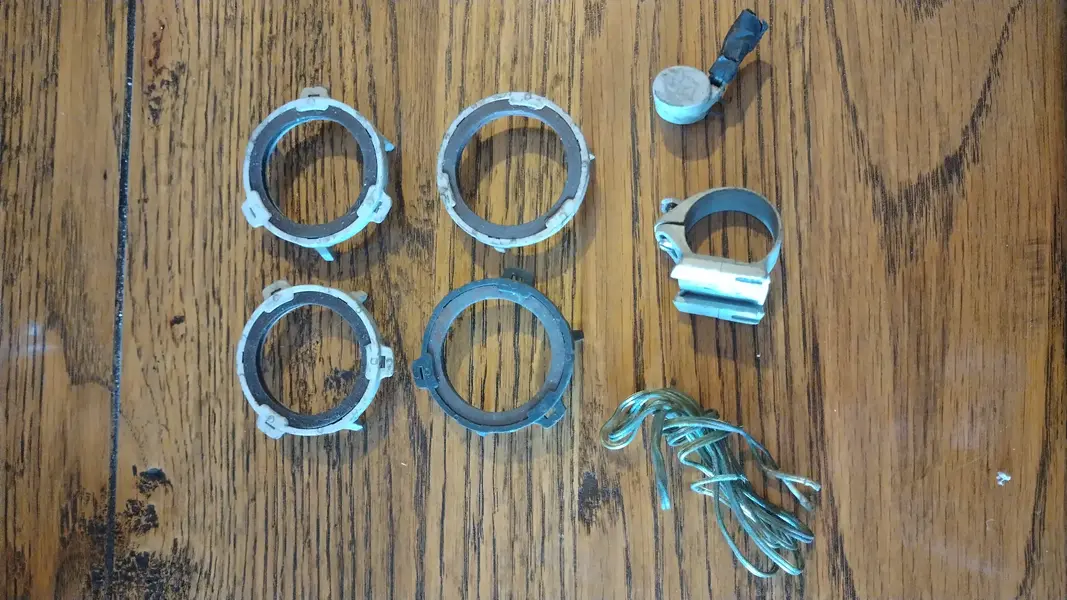
Thank you! I'm definitely game to try again, especially with a different wheel sensor. Will DM you.Hello, I've been having a tidy up of my old bike parts & came across some avocet wheel magnets, sensor, cable & bracket. I will never have a use for these again, you're welcome to have them for the price of a stamp if interested. View attachment 1010708
MuchAlohaNui
Senior Retro Guru
Same mechanism is used on current e-bikes to measure actual ground speed.
Silly question: Have you replaced the battery with a period-correct battery? Some older stuff cannot handle lithium ion. Also the magnet and the coil need to be mounted extremely close to each other.
http://www.avocet.com/instrpdfs/30_31eng.pdf
Silly question: Have you replaced the battery with a period-correct battery? Some older stuff cannot handle lithium ion. Also the magnet and the coil need to be mounted extremely close to each other.
http://www.avocet.com/instrpdfs/30_31eng.pdf
I have a similar problem with an Avocet 30 that came on a bike I recently bought. The previous owner had taken the bike out of storage, replaced the battery, and found it no longer registered speed.
While troubleshooting, I found that the computer appeared to properly register speed when the components were removed from the bicycle, and the sensor was slid around the ring, in direct contact. I could get up to around 15mph in-hand. However, it didn’t register anything when on the bike, with the original 5mm spacing between ring and sensor. Curiously, with the magnet ring on the bike, and the sensor in-hand, held directly against the ring, it only gives inconsistent low speed readings. My suspicion is that the magnet ring has weakened to uselessness, and the axle, fork, and spokes are weakly magnetized.
I’ve ordered a magnet viewing film and a bunch of small neodymium magnets myself to try to build a replacement ring. However, I also fiddled about with a neodymium magnet and my magnet ring, so I doubt I’ll be able to glean the original field configuration from mine. I’d be interested in seeing a magnetic field photo of an unaltered ring, if you get your hands on one.
novocaine
Retro Wizard
the coil is inductive sensor. not disimilar to a hall effect but simpler.
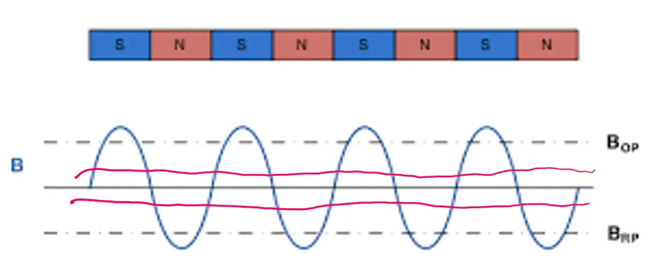
it's a fairly finely tuned sensor. you are on the right lines with your new magnetic ring, but I suspect that your neodymium magnets are too strong. rather than reading at the tip of a curve, you are reading a long way down in to the wave form, so you don't get the dwell time needed for the pulse to be read before you are reading the next one.
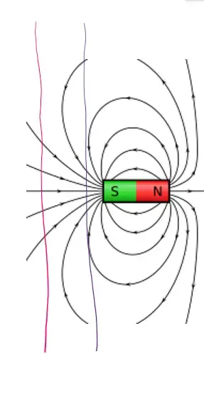
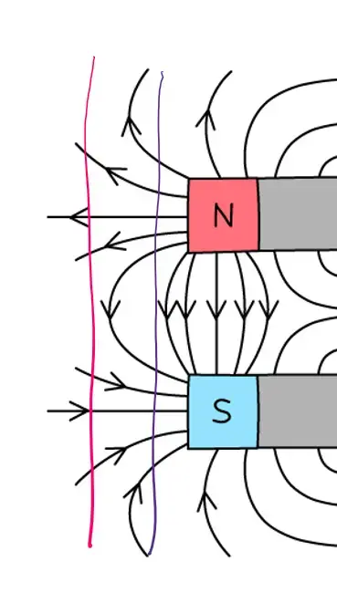
image below to try and help explain my thoughts. the bit you want to read is the red line, the bit you are currently reading is the purple. add in interaction of opposing fields and it gets all kinds of messy. your film shows a lot of interaction between the magnets, so the "0" isn't clean enough for it to delineate transit.

you want to be reading the dashed lines, but because the magnets are so strong you are reading where my red line is. at speed there isn't enough time between the N/S transition for it to read. it's semi error correcting as it will see 2 N 2 S in each transfer, but I don't know if it's that clever. moving the ring away from the sensor will be hard to tune for, better option is a weaker field magnet. it will read as slow speed, but as the wave frequency increases it can't see the transit from North to South so it falls over.

I need to stop, work to do.
it's a fairly finely tuned sensor. you are on the right lines with your new magnetic ring, but I suspect that your neodymium magnets are too strong. rather than reading at the tip of a curve, you are reading a long way down in to the wave form, so you don't get the dwell time needed for the pulse to be read before you are reading the next one.
image below to try and help explain my thoughts. the bit you want to read is the red line, the bit you are currently reading is the purple. add in interaction of opposing fields and it gets all kinds of messy. your film shows a lot of interaction between the magnets, so the "0" isn't clean enough for it to delineate transit.

you want to be reading the dashed lines, but because the magnets are so strong you are reading where my red line is. at speed there isn't enough time between the N/S transition for it to read. it's semi error correcting as it will see 2 N 2 S in each transfer, but I don't know if it's that clever. moving the ring away from the sensor will be hard to tune for, better option is a weaker field magnet. it will read as slow speed, but as the wave frequency increases it can't see the transit from North to South so it falls over.

I need to stop, work to do.
Similar threads
- Replies
- 18
- Views
- 2K

