rmwesley
Retro Guru
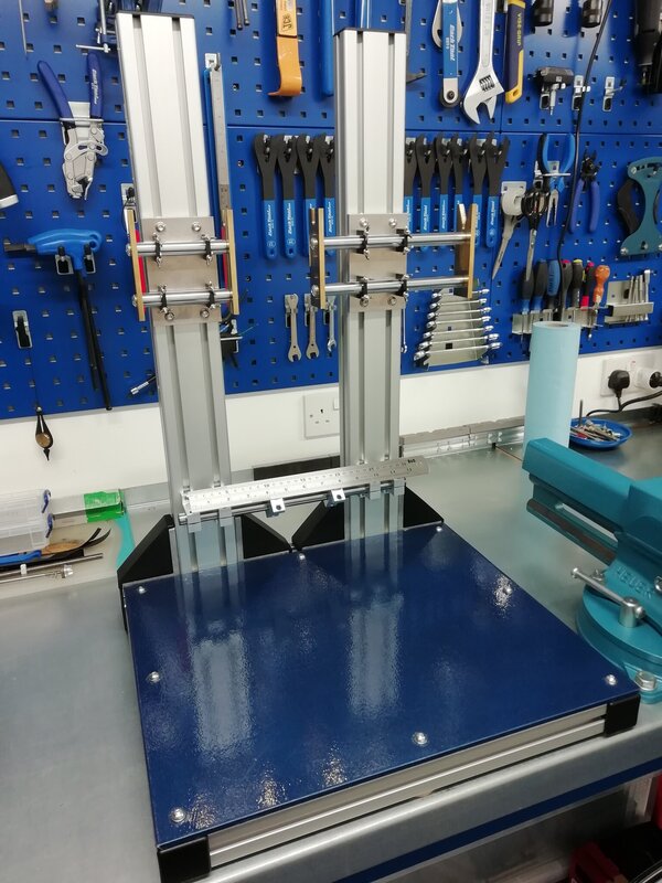
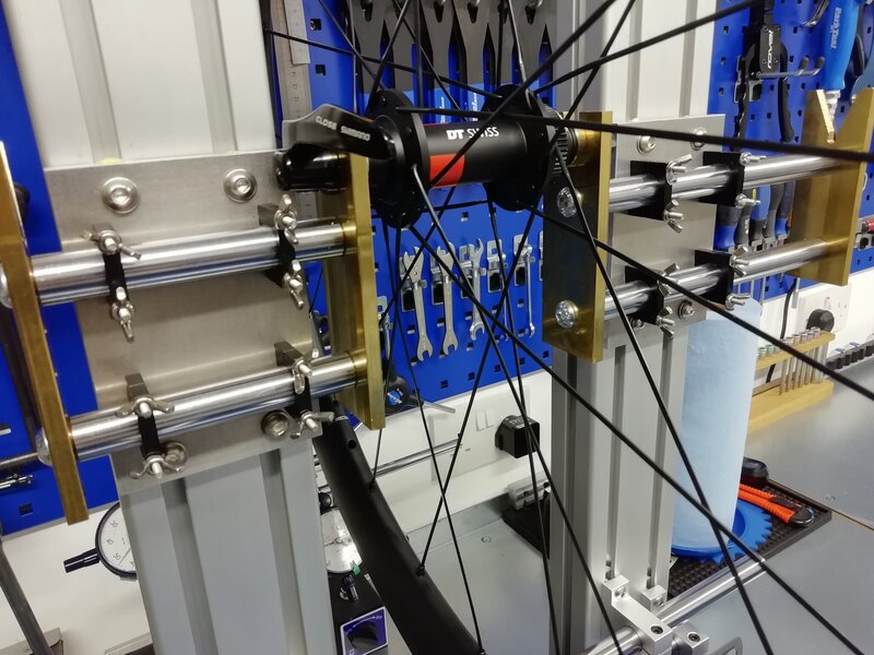
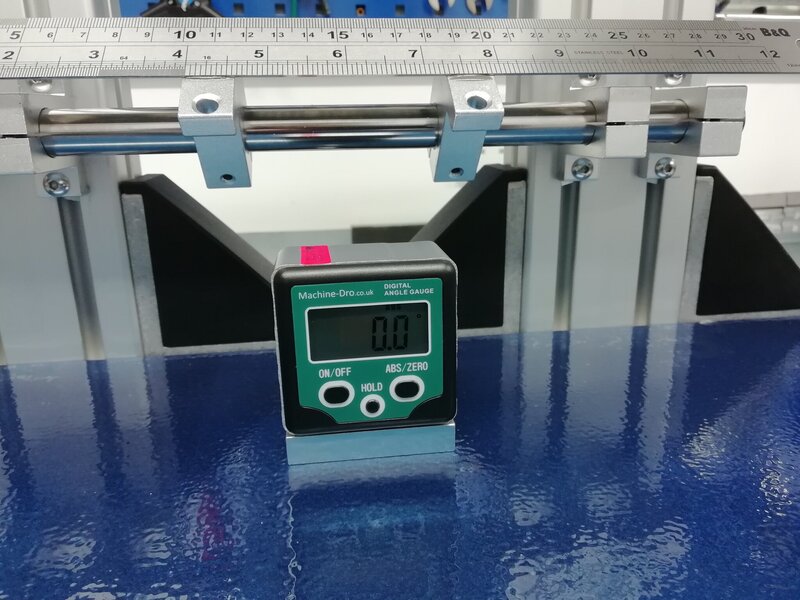
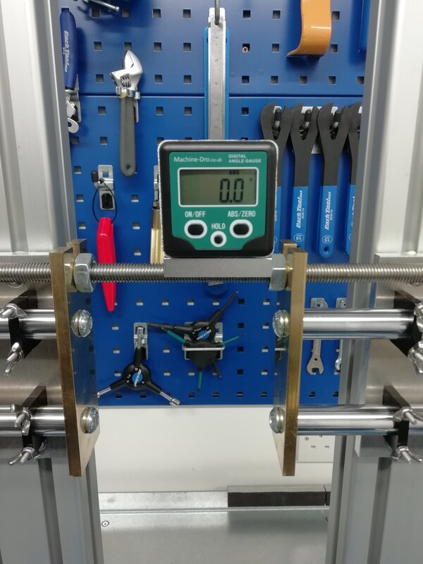
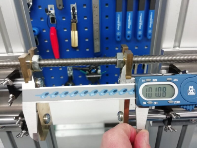
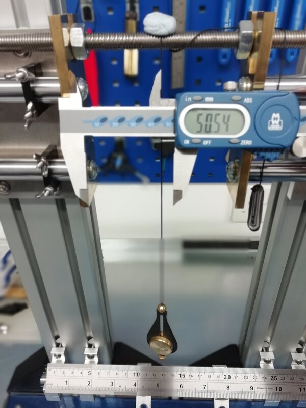
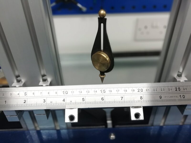
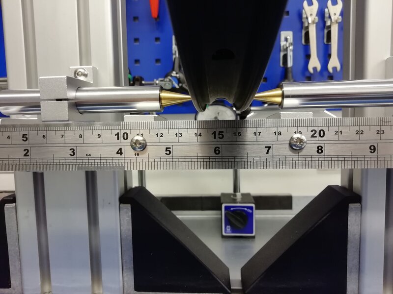
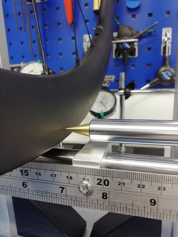
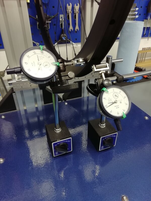
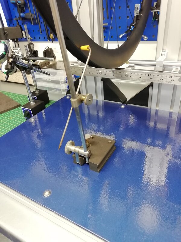
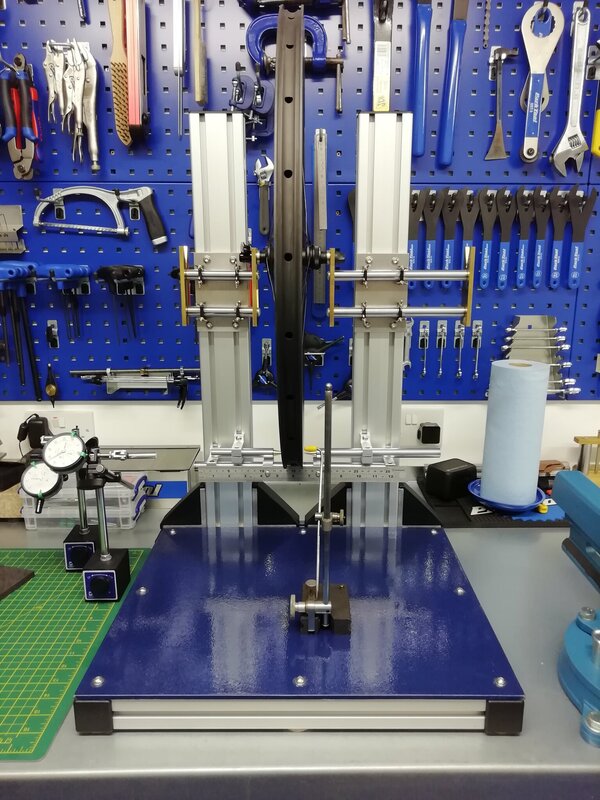
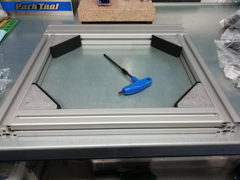
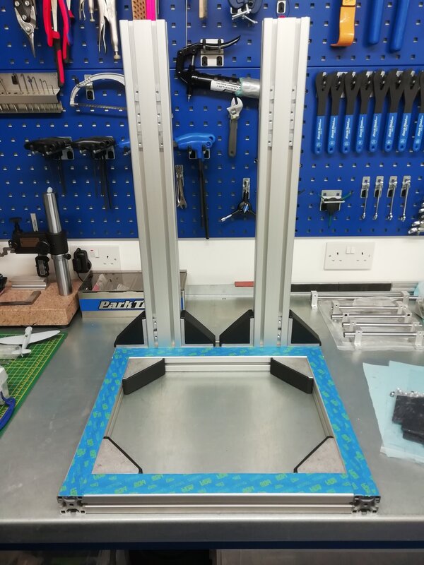
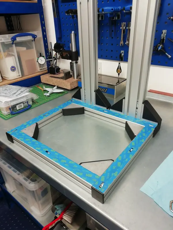
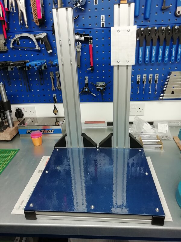
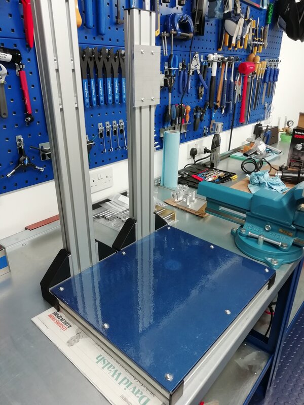
A couple of people asked if I could post up some pics and a parts list for my wheel jig. You might be underwhelmed since it is uber-simple to put together. Hopefully pictures speak a thousand words in terms of how it all goes together. Excluding the DTI gauges I think the whole thing cost less than £200.
The frame is made from aluminium profile purchased from motedis.co.uk. The base is 480mm wide by 440mm deep & the vertical posts are 660mm tall. I've built a few jigs and frames for fish tanks etc. and motedis are by far and away the cheapest / easiest company to deal with if you are only buying small amounts.
Parts
Base (front centre): Profile 40x40L I-Type slot 8 (019600 - 400mm)
Base (left and right): Profile 40x40L I-Type slot 8 (019600 - 360mm)
Base (rear centre): Profile 40x80L I-type slot 8 (019603 - 480mm)
Posts: Profile 40x80L I-type slot 8 (019603 - 660mm)
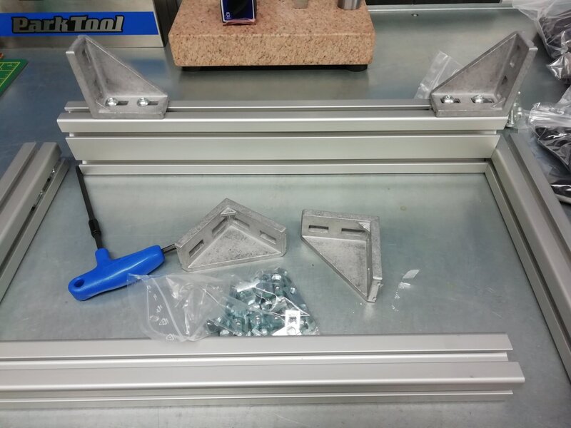
Base brackets: Bracket 40 I-Type slot 8 with fastening set and cover cap (S8IBR40)
Post brackets: Bracket 40x80 I-Type slot 8 with fastening kit and cover cap (S8IBR4080+FS+CC)
Cover caps: Cover Caps 40x80 I-Type slot 8 (091009)
Cover caps: Cover Caps 40x40 I-Type Slot 8 (091007)
Downside is a minimum shipping cost of approx. £15 - £20 for any order, so you can't really afford to miss anything off. I've got bags of nuts, fasteners and brackets & dipped into those for this build, so the list above is probably not exhaustive. If you have a crack yourself, figure out exactly what you need.
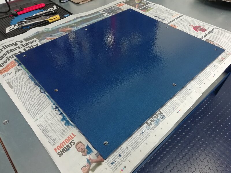
The steel base plate is 480mm wide x 400mm deep x 10mm thick plate covered in Hammerite and bolted onto the frame securely. For this you will need the "Roll-in T-Nut I-Type slot 8" fasteners which go into the profile slots. They come in M4, M5, M6 and M8.
More to follow...


