Hello.
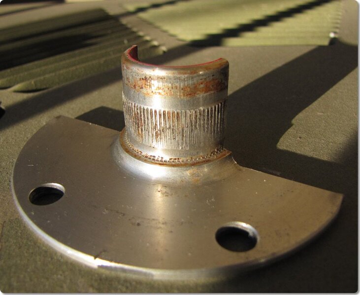
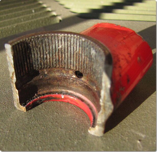
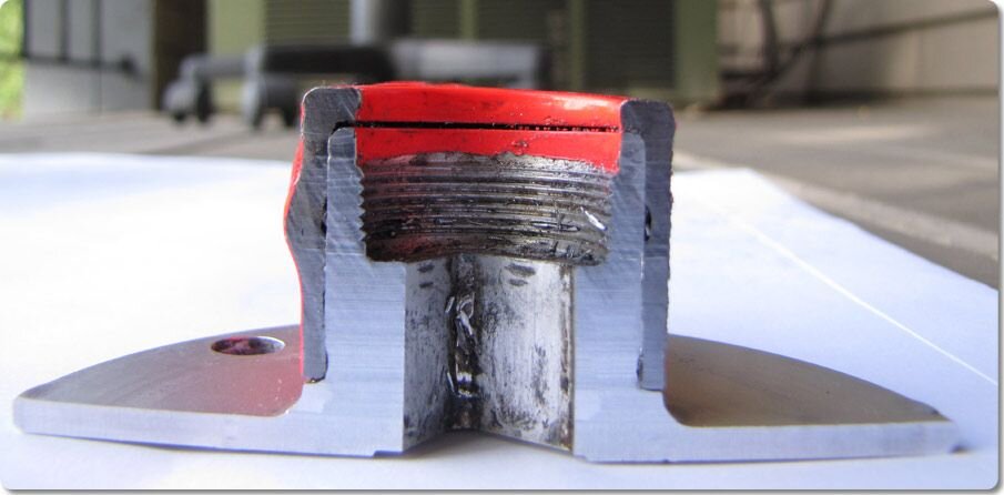
Looking for some advice on my Syncros revolution cranks. I've found some cracks at two of the mounting holes on the "powerplate". Unfortunately in it's earlier life someone drilled and enlarged these holes to allow for regular chainringbolts to be mounted (8 to 10mm). This made the the material at the outer edge quite thin. I won't be riding hard with these, but still use them so I would like to ask what you think?


Instead of relying on the remaining three holes, I thought of machining 5 new M8 holes in the powerplate to allow for mounting a complete circular plate that could replace the spacers, with standard chainring screws (only screw part).
Would adding 5 new holes (marked with purple) make the plate much weaker? it would somewhat be compensated with the new "spacer ring" (gold) in 7075 alu. The 5 new holes will be covered by the standard spider. so won't really be visible from the drive side.


Mounting the small chainring will use standard chainring screw and barrel.


Thanks for looking and looking forward to hear your thoughts.
Looking for some advice on my Syncros revolution cranks. I've found some cracks at two of the mounting holes on the "powerplate". Unfortunately in it's earlier life someone drilled and enlarged these holes to allow for regular chainringbolts to be mounted (8 to 10mm). This made the the material at the outer edge quite thin. I won't be riding hard with these, but still use them so I would like to ask what you think?
Instead of relying on the remaining three holes, I thought of machining 5 new M8 holes in the powerplate to allow for mounting a complete circular plate that could replace the spacers, with standard chainring screws (only screw part).
Would adding 5 new holes (marked with purple) make the plate much weaker? it would somewhat be compensated with the new "spacer ring" (gold) in 7075 alu. The 5 new holes will be covered by the standard spider. so won't really be visible from the drive side.
Mounting the small chainring will use standard chainring screw and barrel.
Thanks for looking and looking forward to hear your thoughts.