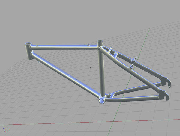
Any designer engineery types on here?

cyfa2809":292thxa4 said:
oh it goes straight to CNC, nice. autocad was always giving me hassle with that! that program and results look very similar to autodesk inventor i think its called. i used to use it. you can create something and change it as you go i.e. change measurements to fit, meaning you dont have to re draw it, you just change it. solid works looks very similar. nice work by the way

Yeah it is similar to inventor. Tis good, so much nicer to use than autodesk
 
We use Solid Edge, and Solid Works for F.E.A.

but to be fair most 3d packages are similar

I'm still yet to find the package that will go straight to CNC, tis a myth

You import the solid model into a CAD/CAM package then create a tool path off it, its not as easy as pressing ONE "do it now" button

Interested to see where this goes
 
NX6

I use Unigraphics - NX 6 at work. We get alot of very large components (65ft long) milled / CNC cut - NX has a CNC bolt on package, but you will pay through the nose for it and as Scrat say I doubt very much that it is a simple as pushing a button and watching the milling machine work it's magic!
 
we used to use edgecam at college, this went straight to cnc but i cant remember if you could render things in it. i think you could. also it let you put in a autocad drawing and then it gives you the cnc code. easy!
 
Interesting to see who the CAD designers/ engineers are out there.

I've moved onto the next page as Jerky's image is huge!! :shock:

Cheers,
Boy"O"boy
 
Interesting to see who the CAD designers/ engineers are out there.

Sometime back, I briefly mentioned I had a scan project underway in this thread here- http://www.retrobike.co.uk/forum/viewto ... c&start=15

In Automotive design, one of the reverse engineering applications we use is called 'Photogrammetry scanning'. We use this to capture surface data ( normally from a clay surface ) and export the files into programs such as Alias, 3d studio and Icemsurf. This can also be exported into CAD/CAM packages to create a cutter path.
This scan of a crankset is part of a project to demonstrate the capabilities of our equipment ( we can't show our day to day stuff!! ). It also helps if your interested in retrobikes :D


The complete scan was completed in around 6hrs and was positioned and rendered using Alias software. The process does not damage the object in anyway... the powder spray wipes off!!

Would any of you be interested in taking this file into your own package and see what's achievable with it? ... basically I'm keen to see how outside suppliers/ engineers deal with our scan quality.

PM me if so.

Cheers,
Boy"O"boy
 

Attachments

  • crank_reverse.jpg
    crank_reverse.jpg
    110.5 KB · Views: 645
  • crank_inside.jpg
    crank_inside.jpg
    58.3 KB · Views: 642
  • crank_detail.jpg
    crank_detail.jpg
    93.1 KB · Views: 631
  • Crankset_full.jpg
    Crankset_full.jpg
    76.8 KB · Views: 631
Here's some more pics of the Photogrammetry process.


Pic. 1
The object to be scanned is covered with reference dots. The 'odd looking' stickers are coded markers. Scale bars laying along side allow the tritop program to determine the size of the object.

Pic. 2
The Coded markers and reference dots are photographed from a number of positions. The images are processed in the Tritop software and provide a digital file of the reference dots. This is accurate to 0.04mm of the actual object.

Pic.3
The reference dots are then scanned to capture the surface data. The scan works by measuring the contrast of the fringe projection ( black lines on surface) against the recognised reference dots.

Pic.4
The Finished scan is processed into polygons and exported in an stl. file.


Cheers,
Boy"O"boy
 

Attachments

  • Aluminium_O_scan.pic2.jpg
    Aluminium_O_scan.pic2.jpg
    65.3 KB · Views: 625
  • Framescan3.jpg
    Framescan3.jpg
    90.6 KB · Views: 625
  • Framescan2.jpg
    Framescan2.jpg
    119.3 KB · Views: 625
  • Framescan1.jpg
    Framescan1.jpg
    142.7 KB · Views: 625
Boy O Boy, Would love a copy of that file. I have used 3D scanners to produce cloud point models before, but never been overly impressed in the accuracy, everything I have tried has needed quite a lot of tidying up manually after scanning, to the point where it may have been quicker to model from scratch.

As for outputting to CNC directly, yes you do still need to do tool path files but most of this is automated and requires a check. Most of my output these days is using rapid prototyping, particulary keen on DMLS technology.

Would love to create a component in Titanium DMLSwith a honeycomb core.
 
JeRkY":fxju7cgj said:
Boy O Boy, Would love a copy of that file. I have used 3D scanners to produce cloud point models before, but never been overly impressed in the accuracy, everything I have tried has needed quite a lot of tidying up manually after scanning, to the point where it may have been quicker to model from scratch.

No problems, PM me your address and I'll get a copy to you. Stl. format ok for you? Each part has been scanned separately and is about 6MB.
This file will also need some cleaning.... The threads for example don't capture very well... although I have done my best to clean up as much of it in the original scan as possible.

cheers,
boy"O"boy
 
:shock:

why was it that when I went to college to do my so called 'electrical & mechanical engineering' and 'Art & Design' courses, nobody mentioned any of this sort of thing.

I expect quality CNC parts very soon.
 
Back
Top