found this a few years ago on tnet someware appologies if its yours
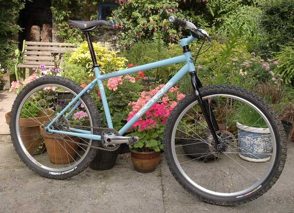
The following presents a method for eccentrically mounting a square taper axle in external bearing cups, thereby enabling adjustment of chain tension. It is intended for use in single speed conversions of frames lacking horizontal dropouts. It permits an alternative approach for those who would prefer built-in chain tensioning over a spring tensioner, particularly if contemplating a fixed gear conversion where a spring tensioner will not work.
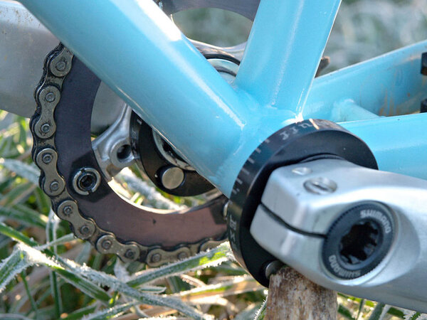
The technique involves drilling and tapping two pairs of holes through the bottom bracket shell into the external bearing cups, in which set screws are placed to secure the cups in adjusted positions. The sealed cartridge bearings are permanently installed eccentrically into the cups using epoxy.
The method features the use of readily available components for the do-it-yourself bike mechanic and it can be done at a minimum of cost. It does not involve too much work nor does it require very great mechanical aptitude.
This method provides for slightly over 1/2" (14mm) of chain length adjustment (7mm eccentric throw). Chain length is adjusted to within this range by the use of a half-link where required. The method is applicable to vertical dropouts, existing wheelsets and square-taper cranksets. It is appropriate to both road and mountain conversions.
INSTRUCTIONS: parts, tools and materials lists, as well as notes and discussion, are found at the end.
[terminology: 'axle'='spindle', BCD=bolt circle diameter, LBS=local bike shop, 'X'=external, ID=inside diameter, OD=outside diameter, ~='approximately', right side=drive-side=chain-side of the bike, JIS and ISO are different common industrial bicycle standards, JIS=Japanese Industrial Standard, ISO=Internacionaleno Standardizio sOmethingorOther]
-Integrated External Bearing Cups:
Cups are obtained from external bearing sets, most cheaply as free discards when bearing sets are replaced. (If you don't have a bike so equipped, hit on friends with external bearing equipped bikes, or friendly LBS personnel as potential sources of discards). Any brand should work. (Race Face X-type and Truvativ Giga-X were used in initial conversions.) The cup threading must match the bike bottom bracket shell threading. English thread is described. Italian thread requires a technique modification explained in the * note.
-Axles and axle length:
The main requirement for axle length is a sufficiently long shaft so that the bearings positioned outside of the bottom bracket shell have adequate extended areas to ride upon. ~8mm of length between the taper and the hub is needed on each side, allowing 2mm wall thickness for the cup and 6mm minimum support for the 7mm wide bearing--16mm total extra axle length required.
The widely available 127mm Shimano axle is is suitable for conversions of 68mm, 70mm and 73mm shells. It is readily removed from an inexpensive cartridge (such as a UN26) and has standard JIS tapers. It has 21mm of excess length.
The shorter 122.5mm axle is minimally adequate for 68mm shells and would be appropriate for road conversions, freewheel cogs or fixed gear cogs, to limit outboard chainline displacement. It may be too short for 70mm Italian thread shells, resulting in the cranks possibly contacting the bearings when fully tightened to place. But this could be remedied by filing or grinding a couple of millimeters of material from the insides of the crankarm bosses. The Sugino 3NN-B axle is 124mm long and may work in a 70mm or 68mm shell. It has bearing cones that would have to be ground down with a bench grinder. Harris Cyclery lists a few longer axles available in their 'hard-to-find' parts section, that might also work for a 73mm shell, and possibly also with ISO tapers or less common crank tapers.
There are chainline adjustment options that can compensate for the increase in axle length.**
--Shimano cartridge disassembly to retrieve the axle:
Remove the rubber axle shaft seals, and the housing seals underneath them, from both sides of the axle, using a hooked pointed tool like a stout dental pick. Remove the nylon bearing retainers from both sides--grasp and pull it with a small needle-nosed pliers or hemostat, or insert a hooked point under an edge directly to one of the balls and pry and pull upward until the flexible nylon retainer pops out.
Push all the bearings (7 on each side) around together to one side of the housing, to the same side on both ends. Snap the axle out of the resulting half-ring arrangements of the balls to the side of the housing. Then push a single middle ball on each side inward out of its race grooves, thereby releasing the axle for removal.
--Bottom Bracket Shell:
Remove the old bottom bracket cartridge or axle and bearings assembly from the bike.
4 screws are tapped through the bottom bracket shell, 2 on each side, to hold the external bearing cups in adjustment. The holes for these screws are placed 13mm (~1/2") in from the shell ends on the bottom of the shell. Space them front and back about 25mm (1") apart. Locate suitable hole positions, lightly center punch them, and drill and tap them for 8-32 screws. A 9/64" bit is often substituted for the standard #29 wire gauge tap bit, but it is slightly larger and may result in shallower threads more prone to stripping. Use the #29 if you have access to one.
Debur the holes inside the shell with emery cloth and a small steel wire brush. Clean out any debris.
--Cups: old bearing removal
Remove the center shield tube from the cup set. Pry the dust seals from the axle holes and outer faces of the old cup bearings, exposing the sealed bearings underneath. Remove the rubber-coated outer wire seal rings from the bearing circumferences.
Some bearings can be removed by driving them out from the inside, tapping around the inner race with a piece of 3/4" dowel or a drift and hammer until they drop out. Support the cup edges on a pair of wooden blocks for this.
If you cannot get a driving tool on the inner race edge, the bearing can be pried out by firmly inserting a thin, flat-blade screwdriver into the groove behind the bearing, angling in through and across the axle hole, and forcefully twisting. Move back and forth across the axle hole, working around the the circumference, firmly inserting and twisting the screwdriver in several different places until the bearing frees up and starts to raise. You can hear a discernable 'click' as you twist each time it moves out slightly. Continue until the bearing is out.
--Cups: preparation
Install the empty cups into the bottom bracket shell. Do not use any cup spacers. Screw them in fully and tighten them to less than 5 ft-lbs. The torque is not critical and should be no more than this, since the cups will be backed off and held in final adjusted positions by the set screws.
Mark the rearmost horizontal position on the cup rims with shallow notches filed into their edges, aligning to a chainstay for reference and centering the notches between two tool grooves.
Try the axle and 6903 bearings into the cups, with the bearings manually held in place against the cup rims to check for interferences that may prevent free axle rotation. Any interferences must be ground or filed out.
Remove the cups from the bike.
--Bearings:
Clean any grease out of the cups and off of the bearing outer circumferences and edges. Place a mark on the rim edge of each bearing with a marking pen. Place a thin film of grease on the bearing seals and inner race.
Place a thin bead of rubber goo or RTV around the outer edge of each bearing on the side without the mark. Place each bearing into a cup with the glue side in, against the cup side wall with the edge mark aligned to the cup edge notch. (See the * note for Italian threads).
Any gap around the outer edges of the bearings into the interior of the threaded part of the cups must be plugged with rubber goo or RTV. It is most easily placed there with a disposable syringe or by dabbing it in with a small brush. (Hot melt glue might work also).
Press each bearing outwards firmly against the inner wall of the outer cup rim. Press each bearing firmly in against the inner cup wall to be sure it is seated flat. Hold the cups and bearings with the gap down for a minute or two until the rubber skins over and will stay in place. Then set them upright, cup side up, and leave them undisturbed until the rubber sealer has firmly gelled (3+hrs).
When the rubber sealer is sufficiently firm, mix the epoxy and place it into the crescent shaped void spaces around the bearings, filling them up flush to the bearing edges. Work the epoxy into the narrow crevices with a pin or small brush. Do not allow epoxy to stray onto the bearing seals. Allow the epoxy to fully harden in a warm place (12+hrs).
After hardening, clean up any stray epoxy or loose sealer and check to be sure the bearings rotate freely.
--Tool holes:
The tool holes are drilled through the outsides of the cup rims, radially inward through the rim metal and through the full depth of the epoxy to the bearings. Locate the holes on flats between tool grooves directly across from the bearings and notches, placed so that the hole will run midway within the epoxy. (see the * note for Italian threads)
INSTALLATION: (see the * note for Italian threads)
Grease the cup threads, but not the inboard 5mm where the set screws will engage.
Use the center shield tube only if it is short enough to fit in the bottom bracket shell without cup spacers and does not interfer with axle rotation. Measure this to be sure.
If the axle can freely slide fully through the bearings, install the cups separately from one another. If the axle cannot slide fully through the bearings and the cups are English threaded, see the *** note.
Crankarm-Axle Spacers:
Align the bearing axle holes with each other, positioned eccentrically to the rear. Grease the axle holes. Lightly grease the axle and place it through the bearings. Clean any grease from the tapers.
'O' rings are placed on the axle between the bearings and crankarms to allow flex room for crank tightening and chain tensioning adjustment. The 'O' rings will compress as the crankarms are tightened to place and will keep the axle from shifting laterally. English thread cups will spread apart and further compress the rings as they are backed out for chain adjustment. The 'O' rings also serve as axle seals to keep moisture and debris out of the bottom bracket shell.
--68mm shell with a 127mm axle: place an 11/16"OD-9/16"ID 'O' ring next to each bearing, and a larger 13/16"OD-9/16"ID 'O' ring outside of it. The larger 'O' ring will help confine the smaller inner ring against the inner bearing race and prevent it from squishing outward onto the seals.
16mm metric washers can substitute for the 13/16"OD-9/16"ID 'O' rings (they have 17mm holes).
--73mm shell or a 122mm axle: place a single 3/4"OD-9/16"ID 'O' ring next to each bearing.
Install the crankarms and fully tighten the left side. When tightening the right chainring side bolt, pause to check the end play each half turn as you approach full tight by forcefully pushing the axle left and right. The end play should disappear in the last full turn or two of tightening, except for a slightly noticeable compressibility of the the 'O' rings. If the end play disappears more than two turns before tight, the compression of the 'O' rings will produce an excessive inward load on the bearings, and possibly also squash the inner 'O' rings outward onto the bearing seals. If so, remove the right crank and replace the thick 'O' ring with the next thinner one. Or replace it with a washer having an inward side hole bevel to help contain the inner 'O' ring. Do this on both sides or just the right side, according to need, and repeat the tightening procedure.
If using 16mm washers as spacers, the inside edges of the holes of the washers can be beveled with a ~2mm bevel, using a 1" round grinding ball and an electric drill. The bevel will partially recess and confine the 'O' rings. You can hold the washers with your fingers while grinding them, but a bench vise works much better.
If there are insufficient gaps for the 'O' rings, the crankarms could come into contact with the bearings as they are tightened, even with the thinnest 'O' rings. If so, you must use a longer axle, or file or grind some material off of the inner surfaces of one or both crankarm bosses, or slightly recess the 'O' ring into the bosses with the grinding ball.
If a gap remains because of an over-long axle, additional 16mm washers can be added as spacers.
Chainline Adjustments:
Remove the rear cassette or freewheel cog cluster to install a single cog, freewheel cog or fixed cog.
First check to be sure that the crank is adjusted perpendicular to the centerline of the bike by laying a straight-edge alongside the chainring and turning the crank to parallel the straight-edge along the down tube. Temporarily secure the crank axle in this position by placing a set screw in a hole on each side of the bottom bracket shell. Then carefully measure and record the distance between the ends of both crankarms and chainstays for future reference. Any difference between the two measurements must be maintained at final chain tensioning to ensure the crank axle is perpendicular to the frame. Note that the crankarms will move an additional 1mm apart over the 1/2 revolution adjustment range for English thread, so that the true space difference between the crankarms will increase a fraction of a millimeter proportional to the amount of adjustment.
The chainline is located by laying the straight-edge alongside the chainring and observing where it intersects the rear hub. It is wise to locate the rear cog slightly inside of the chainline (~2mm), to compensate for frame flexing under the heaviest pedaling loads. This also reduces the need for inboard chainline movement.
For a cassette hub, the cog is located to the chainline by using cassette spacers.
A freewheel or fixed cog can be moved out a few millimeters by using hub spacers.
If you are doing a mountain conversion with a single freewheel cog and need a large correction, and you are using a 110/74mm BCD triple crank, an inner chainring mounting can be used. A new inner 32t/74mm BCD chainring must be obtained for this. Shimano and Sugino make inexpensive ones.
For a road single speed using the outer chainring, the outer ring should be moved to the inner mount, or to the middle position on a triple crank.
The original chainring bolts may be over-long for re-use because of removal of one chainring. This is easily corrected by fitting a suitable washer under the bolt head, but it may require filing one edge of each washer flat if the mount has a shelf. The washers can also be placed between the chainring and crank to gain ~2mm (the washer thickness) inboard movement.
Many chainrings are made with symmetrical tooth profiles and can be run either forward or backward for single speed usage. If the teeth on an outer ring are slightly offset to the outside because of chainring dish, the chainring can be turned around in some cases to gain as much as 2-4mm inboard chainline movement. As a bonus, the backsides of the chainring teeth will be unworn.
Chain Length:
Initial chain tensioning is best done with a new chain. A used chain will work if it has no more than 1/16" stretch over a 12" length (1.5mm over 305mm length).
Remove the set screws from the bottom bracket shell.
Chain length is first set to the nearest whole link. A half-link may be required to bring the chain length into adjustable range. If you have to shorten the chain by a half-link, remove one full link (two teeth) and add back a half-link.
Tension the chain to about 1/2" or less loose play on one side of the chain with the other side held taut. For more information about chain tensioning, see SheldonBrown.com for tips and technique.
When satisfied with the chain tension, place a 1/8" 8-32 set screw in the bottom bracket shell on the chain-side to hold that position. Align the crank axle holes again by checking against the crankarm/chainstay measurements previously noted to assure the axle is perpendicular to the frame and secure it with a set screw on the left side.
To ensure the tension setting does not slip, the two remaining left and right screw holes are drilled and tapped through the inner aluminum cup metal. 3/8" 8-32 cap screws are used in these holes to lock the cups in place. The 3/8" screws may contact the axle if your adjustment position is outside of midrange. If so, file them shorter. Use blue thread-locker on these screws.
Back out the shorter first set screws and add blue thread-locker to them too. Do not drill these holes through at this time.
When subsequent repositioning is needed to compensate for the wear of a new chain--or when a new chain is installed replacing an original worn chain--remove all the set screws and repeat the chain tension procedure. This time move the short set screws to the previously drilled-through holes and just snug them into contact at the proper chain tension. Then drill through the inner cup metal at the previously undrilled screw positions and move the cap screws to these newly-drilled and tapped holes. The two different drillings then will yield two different settings--'new-tight', and 'worn-tight'.
* Italian threads: The bearing mounted in a drive-side cup having Italian threads must be placed on the opposite side of the cup from the left side, 180 degrees from the edge notch. The tool hole must be located adjacent to the notch. When installing, tighten the right cup to 1/2 turn short of full tight and align the axle hole with the left bearing. The right cup will further tighten during chain adjustment, while the left one simultaneously backs out. An axle with no interferences is required, so that the cups and axle can be installed separately.
** Summary of Chainline Movement Options to compensate for a longer crank axle--used singly or combined:
-Position the rear cog 2mm inside of the chainline to compensate for frame flex under heavy pedaling loads
-Hub Spacers--cassette spacers on a freehub, or rear hub spacers with a single cog freewheel or fixed cog
-Use a flat washer between the chainring and crank on chainring bolts, (~2mm gain)
-Use the inner chainring mount on a 74mm BCD triple crank--a new 32t inner chainring will be required
-Road conversions--use the shortest allowable axle, 122mm or 124mm
-Road conversions--move the outer chainring to the inner (double) or middle (triple) position
-Turn the chainring around if it has a symmetrically cut tooth profile that is offset to the outside (~2mm gain)
***Simulaneous English-thread Cup Installation: This method must be used if the axle has shoulders or raised areas that prevent it from sliding fully through the bearings.
The cups may have different thread counts, so that one may need to be started a few turns before the other so they finish tightening together. Count the number of threads and start the greater one in first, turning it in as many turns as it has extra threads. Place the axle through the bearing and slide the other cup and bearing on. Begin to turn the cups in simultaneously, grasping one in each hand and turning them equally to prevent the axle from binding. The cups must tighten to the full-tight position simultaneously. If you find that one cup tightens before the other, you will have to back out and reinstall, altering the number of turns difference.
PARTS LIST: essential items
-External bottom bracket bearing cups, any brand
- 8-32 x 1/8" Allen set screws (2), 8-32 x 3/8" cap screws or button heads (2)
-square-taper axle shaft, 122mm or 127mm, from a Shimano cartridge
-sealed cartridge bearings (2), 17mm(ID) x 30mm(OD) x 7mm, 6903-2RS
-'O' rings--11/16"OD-9/16"ID (2), 13/16"OD-9/16"ID (2), 3/4"OD-9/16"ID (2)
-16mm washers (2), (used with a 68mm hub and 127mm axle)
-chain half-link (KMC brand)
OTHER ITEMS, depending on particular bike conversion details: singlespeed cog, or a BMX freewheel or a fixed cog, new chain, 32t/74mm BCD chainring, cassette spacers
MATERIALS: grease, 'JB Weld' epoxy--or similar (regular set), coarse emory cloth, blue thread-lock, silicone or rubber sealant--such as blue 'RTV', Shoe-Goo, Plumbers-Goop, Marine- Goop, etc.
TOOLS REQUIRED FOR FABRICATION: hammer, screwdriver, dental pick or needle-pointed hook tool, 8-32 tap, electric drill and bit (#29 wire gauge bit best, or 9/64"), center punch, small steel wire 'tooth'brush, ruler (mm/in), 24" straight-edge, disposable glue syringes or a small brush, flat file, and (possibly) a 1" round ball grinding stone drill bit
TOOLS REQUIRED FOR BIKE CONVERSION: metric Allen wrenches, chainring tool, cassette lockring tool or freewheel tool (depending on the type of cog cluster), internal bottom bracket tool (if replacing a cartridge type bottom bracket), crank extractor, chain tool, chain whip, external cup bottom bracket tool (open-end type, a channel-lock can substitute)
A channel-lock pliers can remove bottom bracket lockrings and non-cartridge internal cupsets, and can substitute for a chain whip if an old cassette or freewheel cog cluster is to be discarded--using it will likely damage the cog teeth. A freewheel tool will be needed if you have to remove a newly installed freewheel to add spacers. It is not needed to remove an old freewheel 'destructively' (see SheldonBrown.com for details).
An old freewheel cog or cassette cog can be used temporarily, but they will be worn and they usually are ramped and have short teeth and twist-teeth to enable easy shifting, and so can more easily slip the chain. Get a single speed cog.
Old cassettes can be easily disassembled to salvage their spacers by unscrewing or drilling out the assembly screws or rivets. They have little nubs that come off with a stroke or two with the file. The lockring can be reused with the smallest outboard cog if it is in good shape. Bottom bracket hub spacers usually can also be used as cassette or freewheel or fixed cog spacers.
6903 sealed cartridge bearings and cycling-specific items are available from many cycling sources, such as; JensonUSA, BikeSource, Bikeman, etc. online. All other non-cycling materials are available at hardware stores. Note also that half-links (KMC brand) are most easily found for 3/32" chain (6-7-8 speed chain), although 1/8" are available.
DISCUSSION--PROS AND CONS
As with all such attempts at modification, there are problems that arise.
Several bike tools are required, most of which cyclists who do their own maintainence are likely to already have. Some tool substitutions can be made and are pointed out in the instructions.
A wider bottom bracket axle is needed than whatever the original internal-bearing spindle was. This results in outboard movement of the chainline. There are simple ways to compensate for this or to move it back inboard.**
Pedal tread width ('Q'-factor) is increased. It is minor enough so that pedaling efficiency losses are negligible. More significantly, it can mean that you are more likely to strike the ground with the inside pedal down when leaning steeply into hard cornering. Don't do that. Or, get narrower pedals.
The readily available Shimano axles are milled to slightly under 17mm diameter, producing a very slight shaft play in the cartridge bearings. This is not noticeable in any way while riding, but you can feel the very slight movement by forcefully wiggling the cranks back and forth. The bearings are rugged and it should not affect their life significantly. But it may cause some abrasion on the 'O' rings. Regular maintainence should include inspection for this.
The upside of the lax axle fit is that it makes installation and adjustments very easy.
Shimano axles have the common JIS taper, suitable to a wide range of cranks. This method has thusfar only been attempted with JIS tapered cranks. Axle length requirements may be different with other tapers.
Suitably long used axles should work fine for the conversion, provided their threads are good.
The problem of lack of access to the drive-side cup for adjustment is alleviated by drilling a 'tool' hole into the cup rim, permitting a hex key (Allen wrench) to be used as a lever.
There is a valid concern about easily stripping the threads out of the thin bottom bracket shell metal. Be cautious with tightening forces and use thread-locker. Concern about the security of the adjustment is addressed by tapping through the inner cup metal to lock two screws in, making the setting completely reliable.
The method is reversible. The 4 small holes are the only modification to the bike frame and they are in an unnoticeable area. Should you wish to revert to a previous geared state, they can be plugged with short bonded set screws.
POSTSCRIPT:
There are many unused good old bikes in many cyclist's stables that could be returned to use by conversion to single speed. Many cyclists probably have some attraction to single-speeding lying latent somewhere in their psyche (even techno-wonk gearheads who love all the complicated stuff), but are prevented from giving it a try because of reluctance to acquire a special purpose bike, being unsure if they will really take to it, or how much of their cycling time they would devote to it. Some of these same cyclists may have thought that perhaps they could convert an old bike inexpensively, but have run into obstacles of costs, frame limitations, or ill-suited components. So, once favored old bikes often remain consigned to perpetual storage when newer models are acquired, and are kept as seldom used backups or loaners, or broken down and scavenged for parts, reluctantly sold, or otherwise just forgotten.
This technique offers an additonal conversion option that some may find preferable, thereby returning old rides to welcome use again.
----DW---- 2/12/2008
")